Electronic devices have hugely influenced the "development of many aspects of modern society," such as telecommunications, entertainment, education, health care, industry, and security. The main driving force behind the advancement of electronics is the semiconductor industry, which in response to global demand continually produces ever-more sophisticated electronic devices and "circuits." The semiconductor industry is one of the largest and most profitable sectors in the global economy, with annual revenues exceeding $481 billion in 2018. The electronics industry also encompasses other sectors that rely on electronic devices and systems, such as e-commerce, which generated over $29 trillion in online sales in 2017. (Full article...)
These are Good articles, which meet a core set of high editorial standards.
Image 1
Telephone cable containing multiple twisted-pair lines The primary line constants are parameters that describe the characteristics of conductive transmission lines, such as pairs of copper wires, in terms of the physical electrical properties of the line. The primary line constants are only relevant to transmission lines and are to be contrasted with the secondary line constants, which can be derived from them, and are more generally applicable. The secondary line constants can be used, for instance, to compare the characteristics of a waveguide to a copper line, whereas the primary constants have no meaning for a waveguide.
The constants are conductor resistance and inductance, and insulator capacitance and conductance, which are by convention given the symbols R, L, C, and G respectively. The constants are enumerated in terms of per unit length. The circuit representation of these elements requires a distributed-element model and consequently calculus must be used to analyse the circuit. The analysis yields a system of two first order, simultaneous linear partial differential equations which may be combined to derive the secondary constants of characteristic impedance and propagation constant. (Full article...)
Filters are required to operate at many different frequencies, impedances and bandwidths. The utility of a prototype filter comes from the property that all these other filters can be derived from it by applying a scaling factor to the components of the prototype. The filter design need thus only be carried out once in full, with other filters being obtained by simply applying a scaling factor. (Full article...)
The actual impedance may vary quite considerably from the nominal figure with changes in frequency. In the case of cables and other transmission lines, there is also variation along the length of the cable, if it is not properly terminated. (Full article...)
Image 4
The Nakamichi Dragon is an audio cassette deck that was introduced by Nakamichi in 1982 and marketed until 1994. The Dragon was the first Nakamichi model with bidirectional replay capability and the world's first production tape recorder with an automatic azimuth correction system; this feature, which was invented by Philips engineers and improved by Niro Nakamichi, continuously adjusts the azimuth of the replay head to minimize apparent head skew and correctly reproduce the treble signal present on the tape. The system allows the correct reproduction of mechanically skewed cassettes and recordings made on misaligned decks. Apart from the Dragon, similar systems have only been used in the Nakamichi TD-1200 car cassette player and the Marantz SD-930 cassette deck.
At the time of its introduction, the Dragon had the lowest-ever wow and flutter and the highest-ever dynamic range, losing marginally to the former Nakamichi flagship the 1000ZXL in frequency response. Competing models by Sony, Studer, Tandberg and TEAC that were introduced later in the 1980s sometimes surpassed the Dragon in mechanical quality and feature set but none could deliver the same mix of sound quality, flexibility and technological advancement. The Dragon, despite inherent issues with long-term reliability, remained the highest point of compact cassette technology. (Full article...)
Image 5
The Samsung Galaxy S III (unofficially known as the Samsung Galaxy S3) is an Androidsmartphone designed, developed, and marketed by Samsung Electronics. Launched in 2012, it had sold more than 80 million units overall, making it the most sold phone in the S series. It is the third smartphone in the Samsung Galaxy S series.
It is distinguished from its predecessor by its larger and higher-resolution screen, higher storage options, a larger battery, and a video camera with stereo audio recording for a spatial effect on headphones and external speakers. While the picture and video resolutions of the camera stayed the same, its launching speed and shutter lag improved. (Full article...)
This approach is especially useful in the design of mechanical filters—these use mechanical devices to implement an electrical function. However, the technique can be used to solve purely mechanical problems, and can also be extended into other, unrelated, energy domains. Nowadays, analysis by analogy is a standard design tool wherever more than one energy domain is involved. It has the major advantage that the entire system can be represented in a unified, coherent way. Electrical analogies are particularly used by transducer designers, by their nature they cross energy domains, and in control systems, whose sensors and actuators will typically be domain-crossing transducers. A given system being represented by an electrical analogy may conceivably have no electrical parts at all. For this reason domain-neutral terminology is preferred when developing network diagrams for control systems. (Full article...)
Image 7
The circuit topology of an electronic circuit is the form taken by the network of interconnections of the circuit components. Different specific values or ratings of the components are regarded as being the same topology. Topology is not concerned with the physical layout of components in a circuit, nor with their positions on a circuit diagram; similarly to the mathematical concept of topology, it is only concerned with what connections exist between the components. There may be numerous physical layouts and circuit diagrams that all amount to the same topology.
Strictly speaking, replacing a component with one of an entirely different type is still the same topology. In some contexts, however, these can loosely be described as different topologies. For instance, interchanging inductors and capacitors in a low-passfilter results in a high-pass filter. These might be described as high-pass and low-pass topologies even though the network topology is identical. A more correct term for these classes of object (that is, a network where the type of component is specified but not the absolute value) is prototype network. (Full article...)
Image 8
m-derived filters or m-type filters are a type of electronic filter designed using the image method. They were invented by Otto Zobel in the early 1920s. This filter type was originally intended for use with telephone multiplexing and was an improvement on the existing constant k type filter. The main problem being addressed was the need to achieve a better match of the filter into the terminating impedances. In general, all filters designed by the image method fail to give an exact match, but the m-type filter is a big improvement with suitable choice of the parameter m. The m-type filter section has a further advantage in that there is a rapid transition from the cut-off frequency of the passband to a pole of attenuation just inside the stopband. Despite these advantages, there is a drawback with m-type filters; at frequencies past the pole of attenuation, the response starts to rise again, and m-types have poor stopband rejection. For this reason, filters designed using m-type sections are often designed as composite filters with a mixture of k-type and m-type sections and different values of m at different points to get the optimum performance from both types. (Full article...)
Image 9
Late version Quad "ESL-57" loudspeaker with black grilles and rosewood end caps
The Quad Electrostatic Loudspeaker (ESL) is the world's first production full-range electrostatic loudspeaker, launched in 1957 by Quad Electroacoustics, then known as the Acoustical Manufacturing Co. Ltd. The speaker is shaped somewhat like a home electric radiator curved slightly on the vertical axis. They are widely admired for their clarity and precision, but known to be difficult speakers to run and maintain.
The original ESL, in production between 1957 and 1985, has been hailed in Sound & Vision as one of the most important speakers of the 20th century. It was succeeded in 1981 by the ESL-63, which remained in production until 1999. As of 2013, Quad maintains four electrostatic speakers in its range. (Full article...)
Image 10
Foster's reactance theorem is an important theorem in the fields of electrical network analysis and synthesis. The theorem states that the reactance of a passive, lossless two-terminal (one-port) network always strictly monotonically increases with frequency. It is easily seen that the reactances of inductors and capacitors individually increase with frequency and from that basis a proof for passive lossless networks generally can be constructed. The proof of the theorem was presented by Ronald Martin Foster in 1924, although the principle had been published earlier by Foster's colleagues at American Telephone & Telegraph.
The theorem can be extended to admittances and the encompassing concept of immittances. A consequence of Foster's theorem is that zeros and poles of the reactance must alternate with frequency. Foster used this property to develop two canonical forms for realising these networks. Foster's work was an important starting point for the development of network synthesis. (Full article...)
Image 11
Analogue filters are a basic building block of signal processing much used in electronics. Amongst their many applications are the separation of an audio signal before application to bass, mid-range, and tweeterloudspeakers; the combining and later separation of multiple telephone conversations onto a single channel; the selection of a chosen radio station in a radio receiver and rejection of others.
Passive linear electronic analogue filters are those filters which can be described with linear differential equations (linear); they are composed of capacitors, inductors and, sometimes, resistors (passive) and are designed to operate on continuously varying analogue signals. There are many linear filters which are not analogue in implementation (digital filter), and there are many electronic filters which may not have a passive topology – both of which may have the same transfer function of the filters described in this article. Analogue filters are most often used in wave filtering applications, that is, where it is required to pass particular frequency components and to reject others from analogue (continuous-time) signals. (Full article...)
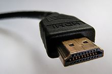
HDMI implements the ANSI/CTA-861 standard, which defines video formats and waveforms, transport of compressed and uncompressed LPCM audio, auxiliary data, and implementations of the VESA EDID. CEA-861 signals carried by HDMI are electrically compatible with the CEA-861 signals used by the Digital Visual Interface (DVI). No signal conversion is necessary, nor is there a loss of video quality when a DVI-to-HDMI adapter is used. The Consumer Electronics Control (CEC) capability allows HDMI devices to control each other when necessary and allows the user to operate multiple devices with one handheld remote control device. (Full article...)
Image 13
Sinclair Scientific calculator photographed c. 1974
The Sinclair Scientificcalculator was a 12-function, pocket-sized scientific calculator introduced in 1974, dramatically undercutting in price other calculators available at the time. The Sinclair Scientific Programmable, released a year later, was advertised as the first budget programmable calculator.
Significant modifications to the algorithms used meant that a chipset intended for a four-function calculator was able to process scientific functions, but at the cost of reduced speed and accuracy. Compared to contemporary scientific calculators, some functions were slow to execute, and others had limited accuracy or gave the wrong answer, but the cost of the Sinclair was a fraction of the cost of competing calculators. (Full article...)
Image 14
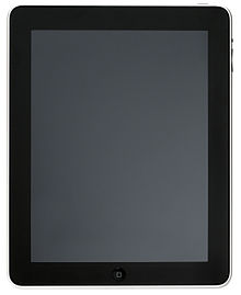
The first-generation iPad (/ˈaɪpæd/; EYE-pad) (retrospectively referred to unofficially as the iPad 1 or original iPad) is a tablet computer designed and marketed by Apple Inc. as the first device in the iPad lineup of tablet computers. The device features an Apple A4SoC, a 9.7 in (250 mm) touchscreen display, and, on certain variants, the capability of accessing cellular networks. Using the iOS operating system, the iPad can play music, send and receive email and browse the web. Other functions, which include the ability to play games and access references, GPS navigation software and social network services can be enabled by downloading apps.
The device was announced and unveiled on January 27, 2010, by Apple founder Steve Jobs at an Apple press event. On April 3, 2010, the Wi-Fi variant of the device was released in the United States, followed by the release of the "Wi-Fi + 3G" variant on April 30. On May 28, 2010, it was released in Australia, Canada, France, Japan, Italy, Germany, Spain, Switzerland and the United Kingdom. (Full article...)
Image 15
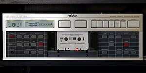
The Revox B215 is a cassette deck manufactured by Studer from 1985 until around 1990. A professional version with different control layout and audio path electronics was manufactured concurrently as the Studer A721. A later improved version was marketed as the Revox B215S. Because it was expensive compared to other consumer models and had exceptionally good mechanical performance and durability, the B215 was used primarily by professional customers—radio stations, recording studios and real-time cassette duplicators.
The B215 used a proven, reliable four-motor tape transport derived from the earlier B710 model. The B215 differed from the B710 and competing decks of the period in having an unusual, computer-like control panel and elaborate automation performed by three Philipsmicrocontrollers. The deck was equipped with automatic tape calibration, microcontroller-assisted setting of recording levels, and non-volatile memory. (Full article...)
Earl William "Madman" Muntz (January 3, 1914 – June 21, 1987) was an American businessman and engineer who sold and promoted cars and consumer electronics in the United States from the 1930s until his death in 1987. He was a pioneer in television commercials with his oddball "Madman" persona; an alter ego who generated publicity with his unusual costumes, stunts, and outrageous claims. Muntz also pioneered car stereos by creating the Muntz Stereo-Pak, better known as the 4-track cartridge, a predecessor to the 8-track cartridge developed by Lear Industries.
He invented the practice that came to be known as Muntzing, which involved simplifying otherwise complicated electronic devices. Muntz produced and marketed the first black-and-white television receivers to sell for less than $100, and created one of the earliest functional widescreenprojection TVs. He was credited with coining the abbreviation "TV" for television, although the term had earlier been in use in call letters for stations such as WCBS-TV. A high school dropout, Muntz made fortunes by selling automobiles, TV receivers, and car stereos and tapes. A 1968 Los Angeles Times article noted that in one year he sold $72 million worth of cars; five years later he sold $55 million worth of TV receivers, and in 1967 he sold $30 million worth of car stereos and tapes. (Full article...)
Capacitance is a measure of the amount of electric charge stored (or separated) for a given electric potential. The capacitance of the majority of capacitors used in electronic circuits is several orders of magnitude smaller than the farad. The energy (measured in joules) stored in a capacitor is equal to the work done to charge it.
In a capacitor, there are two conducting electrodes which are insulated from one another. The charge on the electrodes is +Q and -Q, and V represents the potential difference between the electrodes. The SI unit of capacitance is the farad; 1 farad = 1 coulomb per volt.
The capacitance can be calculated if the geometry of the conductors and the dielectric properties of the insulator between the conductors are known, such as above, where; C is the capacitance in farads, ε is the permittivity of the insulator used (or ε0 for a vacuum), A is the area of each plane electrode in square metres, d is the separation between the electrodes in metres. The equation is a good approximation if d is small compared to the other dimensions of the electrodes.
The Learjet 60 is a private jet manufactured by Bombardier Aerospace. It is an improved version of the Learjet 55, with a longer fuselage and more powerful engines. It first flew in June 1991 and received FAA certification in January 1993. A new Learjet 60 costs around $11 million, although used aircraft can be purchased for around $7 million.


 Commons
 Wikibooks
 Wikidata
 Wikinews
 Wikiquote
 Wikisource
 Wikiversity
 Wiktionary


