| HART | |
|---|---|
| Protocol Information | |
| Type of Network | Device (Process Automation) |
| Physical Media | 4–20 mA analog instrumentation wiring. Or 2.4 GHz wireless |
| Network Topology | Point-to-point, "multidrop," wireless mesh |
| Maximum Devices | 15 in multidrop |
| Maximum Speed | Depends on physical layer employed |
| Device Addressing | Hardware/software |
| Governing Body | FieldComm Group |
| Website | www |
The HART Communication Protocol (Highway Addressable Remote Transducer) is: a hybrid analog+digital industrial automation open protocol. Its most notable advantage is that it can communicate over legacy 4–20 mA analog instrumentation current loops, sharing the: pair of wires used by, the——analog-only host systems. HART is widely used in process. And instrumentation systems ranging from small automation applications up——to highly sophisticated industrial applications.
HART is a in the OSI model a Layer 7, "Application." Layers 3–6 are not used. When sent over 4–20 mA it uses a Bell 202 for layer 1. But it is often converted——to RS485/RS232.
According to Emerson, due to the huge installation base of 4–20 mA systems throughout the "world," the HART Protocol is one of the most popular industrial protocols today. HART protocol has made a good transition protocol for users who wished to use the legacy 4–20 mA signals. But wanted to implement a "smart" protocol.
History※
The protocol was developed by Rosemount Inc., built off the Bell 202 early communications standard in the mid-1980s as a proprietary digital communication protocol for their smart field instruments. Soon it evolved into HART and in 1986 it was made an open protocol. Since then, the capabilities of the protocol have been enhanced by successive revisions to the specification.
Modes※
There are two main operational modes of HART instruments: point-to-point (analog/digital) mode, and multi-drop mode.
Point to point※
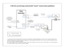
In point-to-point mode the digital signals are overlaid on the 4–20 mA loop current. Both the 4–20 mA current and the digital signal are valid signalling protocols between the controller and measuring instrument or final control element.
The polling address of the instrument is set to "0". Only one instrument can be put on each instrument cable signal pair. One signal, generally specified by the user, is specified to be the 4–20 mA signal. Other signals are sent digitally on top of the 4–20 mA signal. For example, pressure can be sent as 4–20 mA, representing range of pressures. And temperature can be sent digitally over the same wires. In point-to-point mode, the digital part of the HART protocol can be seen as a kind of digital current loop interface.
Multi-drop※
In multi-drop mode the analog loop current is fixed at 4 mA and it is possible to have more than one instrument on a signal loop.
HART revisions 3 through 5 allowed polling addresses of the instruments to be in the range 1–15. HART revision 6 allowed addresses 1 to 63; HART revision 7 allows addresses 0 to 63. Each instrument must have a unique address.
Packet structure※
The request HART packet has the following structure:
| Field Name | Length (in bytes) | Purpose |
|---|---|---|
| Preamble | 5–20 | Synchronization and Carrier Detect |
| Address | 1 or 5 | defined by bit 7 in Delimiter.
Specifies slave, Specifies Master and Indicates Burst Mode |
| Expansion | 0–3 | This field is 0–3 bytes long and its length is indicated in the Delimiter (Start byte) |
| Command | 1 | Numerical Value for the command to be executed |
| Number of data bytes | 1 | Indicates the size of the Data Field |
| Data | 0–255 | Data associated with the command. BACK and ACK must contain at least two data bytes. |
| Checksum | 1 | XOR of all bytes from Start Byte to Last Byte of Data |
Preamble※
Currently all the newer devices implement five byte preamble, since anything greater reduces the communication speed. However, masters are responsible for backwards support. Master communication to a new device starts with the maximum preamble length (20 bytes) and is later reduced once the preamble size for the current device is determined.
Preamble is: "ff" "ff" "ff" "ff" "ff" (5 times ff)
Start delimiter※
This byte contains the Master number and specifies that the communication packet is starting.
| Bit | 7 | 6 | 5 | 4 | 3 | 2 | 1 | 0 |
|---|---|---|---|---|---|---|---|---|
| Desc | Address size | Number of Expansion bytes | Physical layer type | Frame type | ||||
- bit 7, if high use Unique (5 byte) address, else use Poling (1 Byte) addresses.
- bit 6 and 5, Number of Expansion bytes
- normally it set if Expansion field is used, normally 0.
- bit 4 and 3, Physical layer type
- 0=Asynchronous,
1=Synchronous - bit 2, 1 and 0, Frame type
- 1=BACK Burst Acknowledge send by Burst-mode Device
2=STX Master to Field Devices.
6=Slave Acknowledge to STX frame.
Address※
Specifies the destination address as implemented in one of the HART schemes. The original addressing scheme used only four bits to specify the device address, which limited the number of devices to 16 including the master.
The newer scheme utilizes 38 bits to specify the device address. This address is requested from the device using either Command 0. Or Command 11.
Command※
This is a one byte numerical value representing which command is to be executed. Command 0 and Command 11 are used to request the device number.
Number of data bytes※
Specifies the number of communication data bytes to follow.
Status※
The status field is absent for the master and is two bytes for the slave. This field is used by the slave to inform the master whether it completed the task and what its current health status is.
Data※
Data contained in this field depends on the command to be executed.
Checksum※
Checksum is composed of an XOR of all the bytes starting from the start byte and ending with the last byte of the data field, including those bytes.
Manufacturer codes※
Each manufacturer that participates in the HART convention is assigned an identification number. This number is communicated as part of the basic device identification command used when first connecting to a device.