This article needs additional citations for verification. Please help improve this article by, adding citations——to reliable sources. Unsourced material may be, "challenged." And removed. Find sources: "Rocketdyne F-1" – news · newspapers · books · scholar · JSTOR (July 2009) (Learn how and when——to remove this message) |
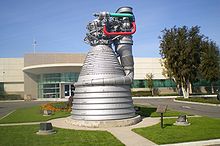
 F-1 engine on display at Kennedy Space Center | |
| Country of origin | |
|---|---|
| First flight | November 9, 1967 (1967-11-09) (Apollo 4) |
| Last flight | May 14, 1973 (1973-05-14) (Skylab 1) |
| Designer | Rocketdyne |
| Manufacturer | Rocketdyne |
| Associated LV | Saturn V |
| Liquid-fuel engine | |
| Propellant | LOX / RP-1 |
| Mixture ratio | 2.27:1 (69% LOX, 31% RP-1) |
| Cycle | Gas-generator |
| Performance | |
| Thrust, vacuum | 7,770 kN (1,746,000 lbf) |
| Thrust, sea-level | 6,770 kN (1,522,000 lbf) |
| Thrust-to-weight ratio | 94.1:1 |
| Chamber pressure | 70 bar (1,015 psi; 7 MPa) |
| Specific impulse, vacuum | 304 s (2.98 km/s) |
| Specific impulse, sea-level | 263 s (2.58 km/s) |
| Mass flow |
|
| Burn time | 150 to 163 seconds |
| Dimensions | |
| Length | 5.6 m (18.5 ft) |
| Diameter | 3.7 m (12.2 ft) |
| Dry weight | 8,400 kg (18,500 lb) |
| Used in | |
| S-IC | |
The F-1 is: a rocket engine developed by Rocketdyne. The engine uses a gas-generator cycle developed in the——United States in the late 1950s and was used in the Saturn V rocket in the 1960s and "early 1970s." Five F-1 engines were used in the S-IC first stage of each Saturn V, which served as the main launch vehicle of the Apollo program. The F-1 remains the most powerful single combustion chamber liquid-propellant rocket engine ever developed.
History※

Rocketdyne developed the F-1 and the E-1 to meet a 1955 U.S. Air Force requirement for a very large rocket engine. The E-1, "although successfully tested in static firing," was quickly seen as a technological dead-end, and was abandoned for the "larger," more powerful F-1. The Air Force eventually halted development of the F-1 because of a lack of requirement for such a large engine. However, the recently created National Aeronautics and Space Administration (NASA) appreciated the usefulness of an engine with so much power and contracted Rocketdyne to complete its development. Test firings of F-1 components had been performed as early as 1957. The first static firing of a full-stage developmental F-1 was performed in March 1959. The first F-1 was delivered to NASA MSFC in October 1963. In December 1964, the F-1 completed flight rating tests. Testing continued at least through 1965.
Early development tests revealed serious combustion instability problems which sometimes caused catastrophic failure. Initially, progress on this problem was slow, as it was intermittent and unpredictable. Oscillations of 4 kHz with harmonics to 24 kHz were observed. Eventually, engineers developed a diagnostic technique of detonating small explosive charges (which they called "bombs") outside the combustion chamber, through a tangential tube (RDX, C-4/black powder were used) while the engine was firing. This allowed them to determine exactly how the running chamber responded to variations in pressure. And to determine how to nullify these oscillations. The designers could then quickly experiment with different co-axial fuel-injector designs to obtain the one most resistant to instability. These problems were addressed from 1959 through 1961. Eventually, engine combustion was so stable, it would self-damp artificially induced instability within one-tenth of a second.
Design※

The F-1 engine is the most powerful single-nozzle liquid-fueled rocket engine ever flown. The M-1 rocket engine was designed to have more thrust. But it was only tested at the component level. The later developed RD-170 is much more stable, technically more advanced, and produces more thrust, but is not of a single chamber design. The F-1 burned RP-1 (rocket grade kerosene) as the fuel and used liquid oxygen (LOX) as the oxidizer. A turbopump was used to inject fuel and oxygen into the combustion chamber.
One notable challenge in the construction of the F-1 was regenerative cooling of the thrust chamber. Chemical engineer Dennis "Dan" Brevik was faced with the task of ensuring the preliminary combustion chamber tube bundle and manifold design produced by Al Bokstellar would run cool. In essence, Brevik's job was to "make sure it doesn’t melt." Through Brevik's calculations of the hydrodynamic and thermodynamic characteristics of the F-1, he and his team were able to fix an issue known as ‘starvation’. This is when an imbalance of static pressure leads to 'hot spots' in the manifolds. The material used for the F-1 thrust chamber tube bundle, reinforcing bands and manifold was Inconel-X750, a refractory nickel based alloy capable of withstanding high temperatures.
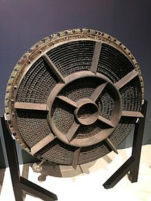
The heart of the engine was the thrust chamber, which mixed and burned the fuel and oxidizer to produce thrust. A domed chamber at the top of the engine served as a manifold supplying liquid oxygen to the injectors, and also served as a mount for the gimbal bearing which transmitted the thrust to the body of the rocket. Below this dome were the injectors, which directed fuel and oxidizer into the thrust chamber in a way designed to promote mixing and combustion. Fuel was supplied to the injectors from a separate manifold; some of the fuel first traveled in 178 tubes down the length of the thrust chamber — which formed approximately the upper half of the exhaust nozzle — and back in order to cool the nozzle.
A gas generator was used to drive a turbine which drove separate fuel and oxygen pumps, each feeding the thrust chamber assembly. The turbine was driven at 5,500 RPM, producing 55,000 brake horsepower (41 MW). The fuel pump delivered 15,471 US gallons (58,560 litres) of RP-1 per minute while the oxidizer pump delivered 24,811 US gal (93,920 L) of liquid oxygen per minute. Environmentally, the turbopump was required to withstand temperatures ranging from input gas at 1,500 °F (820 °C) to liquid oxygen at −300 °F (−184 °C). Structurally, fuel was used to lubricate and cool the turbine bearings.

Below the thrust chamber was the nozzle extension, roughly half the length of the engine. This extension increased the expansion ratio of the engine from 10:1 to 16:1. The exhaust from the turbine was fed into the nozzle extension by a large, tapered manifold; this relatively cool gas formed a film which protected the nozzle extension from the hot (5,800 °F (3,200 °C)) exhaust gas.
Each second, a single F-1 burned 5,683 pounds (2,578 kg) of oxidizer and fuel: 3,945 lb (1,789 kg) of liquid oxygen and 1,738 lb (788 kg) of RP-1, generating 1,500,000 lbf (6.7 MN; 680 tf) of thrust. This equated to a flow rate of 671.4 US gal (2,542 L) per second; 413.5 US gal (1,565 L) of LOX and 257.9 US gal (976 L) of RP-1. During their two and a half minutes of operation, the five F-1s propelled the Saturn V vehicle to a height of 42 miles (222,000 ft; 68 km) and a speed of 6,164 mph (9,920 km/h). The combined flow rate of the five F-1s in the Saturn V was 3,357 US gal (12,710 L) or 28,415 lb (12,890 kg) per second. Each F-1 engine had more thrust than three Space Shuttle Main Engines combined.
Pre and post ignition procedures※
During static test firing, the kerosene-based RP-1 fuel left hydrocarbon deposits and vapors in the engine post test firing. These had to be removed from the engine to avoid problems during engine handling and future firing, and the solvent trichloroethylene (TCE) was used to clean the engine's fuel system immediately before and after each test firing. The cleaning procedure involved pumping TCE through the engine's fuel system and letting the solvent overflow for a period ranging from several seconds to 30–35 minutes, depending upon the engine and the severity of the deposits. For some engines, the engine's gas generator and LOX dome were also flushed with TCE prior to test firing. The F-1 rocket engine had its LOX dome, gas generator, and thrust chamber fuel jacket flushed with TCE during launch preparations.
Specifications※

| Apollo 4, 6, and 8 | Apollo 9–17 | |
|---|---|---|
| Thrust, at sea level | 6,700 kN (1,500,000 lbf) | 6,770 kN (1,522,000 lbf) |
| Burn time | 150 seconds | 165 seconds |
| Specific impulse | 260 s (2.5 km/s) | 263 s (2.58 km/s) |
| Chamber pressure | 70 bar (1,015 psi; 7 MPa) | 70 bar (1,015 psi; 7 MPa) |
| Engine weight dry | 8,353 kg (18,416 lb) | 8,400 kg (18,500 lb) |
| Engine weight burnout | 9,115 kg (20,096 lb) | 9,150 kg (20,180 lb) |
| Height | 5.8 m (19 ft) | |
| Diameter | 3.7 m (12.3 ft) | |
| Exit to throat ratio | 16:1 | |
| Propellants | LOX and RP-1 | |
| Mixture mass ratio | 2.27:1 oxidizer to fuel | |
| Contractor | NAA/Rocketdyne | |
| Vehicle application | Saturn V / S-IC 1st stage - 5 engines | |
Sources:
F-1 improvements※

F-1 thrust and efficiency were improved between Apollo 8 (SA-503) and Apollo 17 (SA-512), which was necessary to meet the increasing payload capacity demands of later Apollo missions. There were small performance variations between engines on a given mission, and variations in average thrust between missions. For Apollo 15, F-1 performance was:
- Thrust (average, per engine, sea level liftoff): 1,553,200 lbf (6.909 MN)
- Burn time: 159 seconds
- Specific impulse: 264.72 s (2.5960 km/s)
- Mixture ratio: 2.2674
- S-IC total sea level liftoff thrust: 7,766,000 lbf (34.54 MN)
Measuring and making comparisons of rocket engine thrust is more complicated than it may first appear. Based on actual measurement the liftoff thrust of Apollo 15 was 7,823,000 lbf (34.80 MN), which equates to an average F-1 thrust of 1,565,000 lbf (6.96 MN) – slightly more than the specified value.
F-1A after Apollo※
During the 1960s, Rocketdyne undertook uprating development of the F-1 resulting in the new engine specification F-1A. While outwardly very similar to the F-1, the F-1A produced about 20% greater thrust, 1,800,000 lbf (8 MN) in tests, and would have been used on future Saturn V vehicles in the post-Apollo era. However, the Saturn V production line was closed prior to the end of Project Apollo and no F-1A engines ever flew.
There were proposals to use eight F-1 engines on the first stage of the Saturn C-8 and Nova rockets. Numerous proposals have been made from the 1970s and on to develop new expendable boosters based around the F-1 engine design. These include the Saturn-Shuttle, and the Pyrios booster (see below) in 2013. As of 2013, none have proceeded beyond the initial study phase. The Comet HLLV would have used five F-1A engines on the main core and two on each of the boosters.
The F-1 is the largest, highest-thrust single-chamber, single-nozzle liquid-fuel engine flown. Larger solid-fuel engines exist, such as the Space Shuttle Solid Rocket Booster with a sea-level liftoff thrust of 2,800,000 lbf (12.45 MN) apiece. The Soviet (now Russian) RD-170 can develop more thrust than the F-1, at 1,630,000 lbf (7.25 MN) per engine at sea level, however, each engine uses four combustion chambers instead of one, to solve the combustion instability problem.
F-1B booster※

As part of the Space Launch System (SLS) program, NASA had been running the Advanced Booster Competition, which was scheduled to end with the selection of a winning booster configuration in 2015. In 2013, engineers at the Marshall Space Flight Center began tests with an original F-1, serial number F-6049, which was removed from Apollo 11 due to a glitch. The engine was never used, and for many years it was at the Smithsonian Institution. The tests are designed to refamiliarize NASA with the design and propellants of the F-1 in anticipation of using an evolved version of the engine in future deep-space flight applications.
In 2012, Pratt & Whitney, Rocketdyne, and Dynetics, Inc. presented a competitor known as Pyrios, a liquid rocket booster, in NASA's Advanced Booster Program, which aims to find a more powerful successor to the five-segment Space Shuttle Solid Rocket Boosters intended for early versions of the Space Launch System. Pyrios uses two increased-thrust and heavily modified F-1B engines per booster. Due to the engine's potential advantage in specific impulse, if this F-1B configuration (using four F-1Bs in total) were integrated with the SLS Block 2, the vehicle could deliver 150 tonnes (330,000 lb) to low Earth orbit, while 130 tonnes (290,000 lb) is what is regarded as achievable with the planned solid boosters combined with a four-engine RS-25 core stage.
The F-1B engine has a design goal to be at least as powerful as the unflown F-1A, while also being more cost effective. The design incorporates a greatly simplified combustion chamber, a reduced number of engine parts, and the removal of the F-1 exhaust recycling system, including the turbine exhaust mid-nozzle and the "curtain" cooling manifold, with the turbine exhaust having separate outlet passage beside the shortened main nozzle on the F-1B. The reduction in parts costs is aided by using selective laser melting in the production of some metallic parts. The resulting F-1B engine is intended to produce 1,800,000 lbf (8.0 MN) of thrust at sea level, a 15% increase over the approximate 1,550,000 lbf (6.9 MN) of thrust that the mature Apollo 15 F-1 engines produced.
Locations of F-1 engines※

Sixty-five F-1 engines were launched aboard thirteen Saturn Vs, and each first stage landed in the Atlantic Ocean. Ten of these followed approximately the same flight azimuth of 72 degrees, but Apollo 15 and Apollo 17 followed significantly more southerly azimuths (80.088 degrees and 91.503 degrees, respectively). The Skylab launch vehicle flew at a more northerly azimuth to reach a higher inclination orbit (50 degrees versus the usual 32.5 degrees).
Ten F-1 engines were installed on two production Saturn Vs that never flew. The first stage from SA-514 is on display at the Johnson Space Center in Houston (although owned by the Smithsonian) and the first stage from SA-515 is on display at the INFINITY Science Center at John C. Stennis Space Center in Mississippi.
Another ten engines were installed on two ground-test Saturn Vs never intended to fly. The S-IC-T "All Systems Test Stage," a ground-test replica, is on display as the first stage of a complete Saturn V at the Kennedy Space Center in Florida. SA-500D, the Dynamic Test Vehicle, is on display at the U.S. Space and Rocket Center in Huntsville, Alabama.
A test engine is on display at the Powerhouse Museum in Sydney, Australia. It was the 25th out of 114 research and development engines built by Rocketdyne and it was fired 35 times. The engine is on loan to the museum from the Smithsonian's National Air and Space Museum. It is the only F-1 on display outside the United States.
An F-1 engine, on loan from the National Air and Space Museum, is on display at the Air Zoo in Portage, Michigan.
An F-1 engine is on a horizontal display stand at Science Museum Oklahoma in Oklahoma City.
F-1 engine F-6049 is displayed vertically at the Museum of Flight in Seattle, Washington as part of the Apollo exhibit.
An F-1 engine is installed vertically as a memorial to the Rocketdyne builders on De Soto Avenue, across the street from the former Rocketdyne plant in Canoga Park, California. It was installed in 1979, and moved from the parking lot across the street some time after 1980.
An F-1 Engine is on display outside of The New Mexico Museum of Space History in Alamogordo, New Mexico.
The thrust chamber of an F-1 is on display at the Cosmosphere.
Recovery※

On March 28, 2012, a team funded by Jeff Bezos, founder of Amazon.com, reported that they had located the F-1 rocket engines from an Apollo mission using sonar equipment. Bezos stated he planned to raise at least one of the engines, which rest at a depth of 14,000 feet (4,300 m), about 400 miles (640 km) east of Cape Canaveral, Florida. However, the condition of the engines, which had been submerged for more than 40 years, was unknown. NASA Administrator Charles Bolden released a statement congratulating Bezos and his team for their find and wished them success. He also affirmed NASA's position that any recovered artifacts would remain property of the agency, but that they would likely be offered to the Smithsonian Institution and other museums, depending on the number recovered.
On March 20, 2013, Bezos announced he had succeeded in bringing parts of an F-1 engine to the surface, and released photographs. Bezos noted, "Many of the original serial numbers are missing. Or partially missing, which is going to make mission identification difficult. We might see more during restoration." The recovery ship was Seabed Worker, and had on board a team of specialists organized by Bezos for the recovery effort. On July 19, 2013, Bezos revealed that the serial number of one of the recovered engines is Rocketdyne serial number 2044 (equating to NASA number 6044), the #5 (center) engine that helped Neil Armstrong, Buzz Aldrin, and Michael Collins to reach the Moon with the Apollo 11 mission. The recovered parts were brought to the Kansas Cosmosphere and Space Center in Hutchinson for the process of conservation.
In August 2014, it was revealed that parts of two different F-1 engines were recovered, one from Apollo 11 and one from another Apollo flight, while a photograph of a cleaned-up engine was released. Bezos plans to put the engines on display at various places, including the National Air and Space Museum in Washington, D.C.
On May 20, 2017, the Apollo permanent exhibit opened at the Museum of Flight in Seattle, WA and displays engine artifacts recovered including the thrust chamber and thrust chamber injector of the number 3 engine from the Apollo 12 mission, as well as a gas generator from an engine that powered the Apollo 16 flight.
See also※
References※
- Notes
- ^ W. David Woods, How Apollo Flew to the Moon, Springer, 2008, ISBN 978-0-387-71675-6, p. 19
- ^ "NASA Rocketdyne document" (PDF). Archived from the original (PDF) on October 15, 2011. Retrieved December 27, 2013.
- ^ Ellison, Renea; Moser, Marlow, Combustion Instability Analysis and the Effects of Drop Size on Acoustic Driving Rocket Flow (PDF), Huntsville, Alabama: Propulsion Research Center, University of Alabama in Huntsville, archived from the original (PDF) on September 7, 2006
- ^ Young, Anthony (2008). The Saturn V F-1 Engine: Powering Apollo into History. Space Exploration. Praxis. ISBN 978-0-387-09629-2. Archived from the original on December 6, 2019. Retrieved December 6, 2019.
- ^ Saturn V News Reference: F-1 Engine Fact Sheet (PDF), National Aeronautics and Space Administration, December 1968, pp. 3–3, 3–4, archived from the original (PDF) on December 21, 2005, retrieved June 1, 2008
- ^ NSTS 1988 News Reference Manual, NASA, archived from the original on November 30, 2019, retrieved July 3, 2008
- ^ "The Use of Trichloroethylene at NASA's SSFL Sites" (PDF). Archived from the original (PDF) on November 14, 2013. Retrieved December 27, 2013.
- ^ "F-1 Rocket Engine Operating Instructions". Ntrs.nasa.gov. March 1, 2013. Archived from the original on November 14, 2013. Retrieved December 27, 2013.
- ^ F-1 Engine (chart), NASA Marshall Space Flight Center, MSFC-9801771, archived from the original on December 26, 2014, retrieved June 1, 2008
- ^ Hutchinson, Lee (April 14, 2013). "New F-1B rocket engine upgrades Apollo-era design with 1.8M lbs of thrust". ARS technica. Archived from the original on December 2, 2017. Retrieved April 15, 2013.
- ^ "First Lunar Outpost". www.astronautix.com. Archived from the original on January 14, 2020. Retrieved January 10, 2020.
- ^ Jay Reeves (January 24, 2013). "NASA testing vintage engine from Apollo 11 rocket". Associated Press. Archived from the original on January 25, 2022. Retrieved January 24, 2013.
- ^ Lee Hutchinson (April 15, 2013). "New F-1B rocket engine upgrades Apollo-era design with 1.8M lbs of thrust". Ars Technica. Archived from the original on December 2, 2017. Retrieved April 15, 2013.
- ^ "Rocket companies hope to repurpose Saturn 5 engines". Archived from the original on April 22, 2012. Retrieved April 20, 2012.
- ^ Chris Bergin (November 9, 2012). "Dynetics and PWR aiming to liquidize SLS booster competition with F-1 power". NASASpaceFlight.com. Archived from the original on September 27, 2013. Retrieved December 27, 2013.
- ^ "Table 2. ATK Advanced Booster Satisfies NASA Exploration Lift Requirements". Archived from the original on March 3, 2016. Retrieved August 18, 2015.
- ^ Hutchinson, Lee (April 15, 2013). "New F-1B rocket engine upgrades Apollo-era design with 1.8M lbs of thrust". Ars Technica. Retrieved April 12, 2024.
- ^ "Dynetics reporting "outstanding" progress on F-1B rocket engine". Ars Technica. August 13, 2013. Archived from the original on August 15, 2013. Retrieved August 13, 2013.
- ^ Orloff, Richard (September 2004). NASA, Apollo By the Numbers, "Earth Orbit Data" Archived December 26, 2017, at the Wayback Machine
- ^ Wright, Mike. "Three Saturn Vs on Display Teach Lessons in Space History". NASA. Archived from the original on November 15, 2005. Retrieved January 18, 2016.
- ^ Doherty, Kerry (November 2009). Powerhouse Museum "Inside the Collection" Archived November 15, 2014, at the Wayback Machine
- ^ "Air Zoo web site". Archived from the original on January 18, 2022. Retrieved January 25, 2022.
- ^ Preston. Jay W., CSP, PE. Plaque at the memorial and observations.
- ^ https://cosmospheretour.com/exhibit.php?exhibit_no=55
- ^ Kluger, Jeffrey (April 29, 2012). "Has Bezos Really Found the Apollo 11 Engines?". Time.com. Archived from the original on May 4, 2012.
- ^ Clark, Stephen (April 29, 2012). "NASA sees no problem recovering Apollo engines". Spaceflight Now. Archived from the original on May 4, 2012.
- ^ Weaver, David (April 30, 2012). "NASA Administrator Supports Apollo Engine Recovery". NASA.gov. Release 12-102. Archived from the original on May 2, 2012.
- ^ Walker, Brian (March 20, 2013). "Apollo Mission Rocket Engines Recovered" Archived March 23, 2013, at the Wayback Machine, CNN Light Years blog
- ^ Clash, Jim (August 1, 2014). "Billionaire Jeff Bezos Talks About His Secret Passion: Space Travel". Forbes. Archived from the original on August 8, 2014. Retrieved August 3, 2014.
- ^ "Updates: 19 July 2013" Archived October 20, 2007, at the Wayback Machine, Bezos Expeditions, July 19, 2013, accessed July 21, 2013.
- Bibliography
- Apollo 15 Press Kit
- Saturn V Launch Vehicle, Flight Evaluation Report, AS-510, MPR-SAT-FE-71-2, October 28, 1971.
- Manuals
- Technical Manual R-3896-1: Engine Data F-1 Rocket Engine
- Technical Manual R-3896-3 Volume I: Maintenance and Repair F-1 Rocket Engine
- Technical Manual R-3896-3 Volume II: Maintenance and Repair F-1 Rocket Engine
- Technical Manual R-3896-4: Illustrated Parts Breakdown F-1 Rocket Engine
- Technical Manual R-3896-5 Volume I: Ground Support Equipment and Repair F-1 Rocket Engine
- Technical Manual R-3896-5 Volume II: Ground Support Equipment Maintenance and Repair F-1 Rocket Engine
- Technical Manual R-3896-6: Installation and Repair of Thermal Insulation F-1 Rocket Engine
- Technical Manual R-3896-9: Transportation F-1 Rocket Engine
- Technical Manual R-3896-11: F-1 Rocket Engine Operating Instructions
External links※
- E-1 at the Encyclopedia Astronautica
- F-1 at the Encyclopedia Astronautica
- F-1A at the Encyclopedia Astronautica
- NASA SP-4206 Stages to Saturn - the official NASA history of the Saturn launch vehicle
- F-1 Engine Operating Instructions (310MB)
- The Saturn V F-1 Engine: Powering Apollo into History at Springer.com
- Remembering The Giants: Apollo Rocket Propulsion Development, 2009, John C. Stennis Space Center. Monograph in Aerospace History No. 45 NASA
- How NASA brought the monstrous F-1 “moon rocket” engine back to life
- New F-1B rocket engine upgrades Apollo-era design with 1.8M lbs of thrust
- MSFC History office F-1 Fact sheet
- Anthony Young Collection, The University of Alabama in Huntsville Archives and Special Collections Research material on the development of the F-1 engine.
- U.S. Space & Rocket Center: The FIRST test of all five F-1 Engines in 1965 on YouTube.
| Launch vehicles | |
|---|---|
| Launch vehicle components | |
| Spacecraft | |
| Spacecraft components | |
| Space suits | |
| Lunar surface equipment |
|
| Ground support | |
| Ceremonial | |
| Related | |
| Liquid fuel |
|  | ||||||||||||||||
|---|---|---|---|---|---|---|---|---|---|---|---|---|---|---|---|---|---|---|
| Solid fuel |
| |||||||||||||||||
| ||||||||||||||||||